There may be cases where you need to prefer one route over another route from a neighboring device with redundant links. For example; latency, bandwidth, etc… This lab will discuss and demonstrate the configuration and verification of RIP route offset lists.
Real World Application & Core Knowledge
If you take a look back at Lab 6-3 – Configuring a Static Floating Route; the lab objectives were that the point-to-point T1 link between R1 and R2 was used as a backup link and the company had to pay per MB transferred over the link; so a floating route was created to ensure the link would only be used in case the main frame relay link between R1 and R2 went down.
If you view the routing table on R1 in lab 7-8 you see that a lot of the networks such as 10.70.20.0/24 and 10.30.0.0/22 are load balanced over the frame-relay link and the point-to-point T1 link. In this lab you will learn how to configure RIP so that the metrics of all routes being transmitted or received over the point-to-point T1 link between R1 and R2 are higher therefore less preferred by RIP thus not being installed into the routing table as the best metric would be the Frame-relay link between R1 and R2.
To complete that task you’ll need to configure what is known as a RIP route metric offset-list. The offset-list takes specific routes that is matches to an ACL and increases the metric by a specified number in the rip statement.
First off you’ll want to create a standard named access-list which matches the routes you want to have impacted by the offset list. In this lab interface Serial0/1 on R1 is only a backup link you’d match ALL routes learned via that interface using the any statement in the standard named ACL.
After the ACL has been created then you configure the offset-list in RIP router configuration mode. You specify the offset-list ACL name then a metric number to be added to the current learned metric and then the direction of which the offset-list is applied and lastly you have the ability to bind the offset list to a specific interface; for this lab it’ll be the backup T1 link between R1 and R2.
The syntax of the offset-list configuration is offset-list ACLNAME in|out metric# interface#/#; an example you’d potentially see on a Cisco router could be offset-list RIP_OFFSET in 5 Serial0/0 which states any routes learned via Serial0/0 that match the networks permitted in the RIP_OFFSET ACL then add +5 to the metric.
This lab will continue to build upon the same logical topology used previously in Lab 7-8 as shown below;
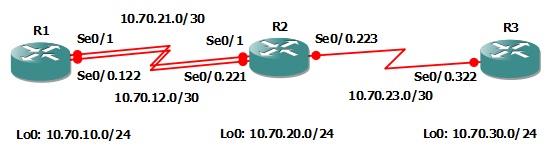 In this lab you will configure a bi-directional offset list on R1 to prevent the point-to-point T1 link between R1 and R2 from load balancing and only be used if the primary frame-relay link fails.
Familiarize yourself with the following new command(s);
| Command | Description |
|---|---|
| offset-list ACL in|out # interface#/# | This command is executed in RIP router configuration mode to assign an ACL to an offset list specifying the metric at which to be added to routes matching the ACL as well as the direction and the interface at which the offset-list is bound to. |
Lab Prerequisites
- If you are using GNS3 than load the Free CCNA Workbook GNS3 topology than start devices; R1, R2 and R3.
- Establish a console session with devices R1, R2 and R3 than load the initial configurations provided below by copying the config from the textbox and pasting it into the respected routers console.
!##################################################
!# Free CCNA Workbook Lab 7-9 R1 Initial Config #
!##################################################
!
enable
configure terminal
!
hostname R1
!
interface Loopback0
description ### SIMULATED NETWORK ###
ip address 10.70.10.1 255.255.255.0
!
interface Serial0/0
description ### PHYSICAL FRAME RELAY INTERFACE ###
no ip address
encapsulation frame-relay
serial restart-delay 0
no frame-relay inverse-arp
!
interface Serial0/0.122 point-to-point
description ### FRAME RELAY LINK TO R2 ###
ip address 10.70.12.1 255.255.255.252
frame-relay interface-dlci 122
!
interface Serial0/0
no shut
!
interface Serial0/1
description ### PPP Link TO R2 ###
ip address 10.70.21.1 255.255.255.252
encapsulation ppp
serial restart-delay 0
clock rate 128000
no shut
!
exit
!
router rip
no auto-summary
version 2
network 10.0.0.0
timers basic 30 40 10 60
passive-interface serial0/1
neighbor 10.70.21.2
!
end
!##################################################
!# Free CCNA Workbook Lab 7-9 R2 Initial Config #
!##################################################
!
enable
configure terminal
!
hostname R2
!
interface Loopback0
description ### SIMULATED NETWORK ###
ip address 10.70.20.1 255.255.255.0
!
interface Serial0/0
description ### PHYSICAL FRAME RELAY INTERFACE ###
no ip address
encapsulation frame-relay
serial restart-delay 0
no frame-relay inverse-arp
!
interface Serial0/0.221 point-to-point
description ### FRAME RELAY LINK TO R1 ###
ip address 10.70.12.2 255.255.255.252
frame-relay interface-dlci 221
ip rip triggered
ip rip send version 1 2
ip rip receive version 1 2
!
interface Serial0/0.223 point-to-point
description ### FRAME RELAY LINK TO R3 ###
ip address 10.70.23.1 255.255.255.252
frame-relay interface-dlci 223
!
interface Serial0/0
no shut
exit
!
interface Serial0/1
description ### PPP LINK TO R1 ###
ip address 10.70.21.2 255.255.255.252
encapsulation ppp
serial restart-delay 0
clock rate 128000
no shut
exit
!
router rip
no auto-summary
version 2
network 10.0.0.0
timers basic 30 40 10 60
passive-interface serial0/1
neighbor 10.70.21.1
!
end
!##################################################
!# Free CCNA Workbook Lab 7-9 R3 Initial Config #
!##################################################
!
enable
configure terminal
!
hostname R3
!
interface Loopback0
description ### SIMULATED NETWORK ###
ip address 10.70.30.1 255.255.255.0
!
interface Loopback103000
ip address 10.30.0.1 255.255.255.0
!
interface Loopback103010
ip address 10.30.1.1 255.255.255.0
!
interface Loopback103020
ip address 10.30.2.1 255.255.255.0
!
interface Loopback103030
ip address 10.30.3.1 255.255.255.0
!
interface Serial0/0
description ### PHYSICAL FRAME RELAY INTERFACE ###
no ip address
encapsulation frame-relay
serial restart-delay 0
no frame-relay inverse-arp
no ip split-horizon
!
interface Serial0/0.322 point-to-point
description ### FRAME RELAY LINK TO R2 ###
ip address 10.70.23.2 255.255.255.252
frame-relay interface-dlci 322
ip rip advertise 10
ip rip triggered
ip rip send version 1 2
ip rip receive version 1 2
ip summary-address ip 10.30.0.0 255.255.252.0
!
interface Serial0/0
no shut
exit
!
router rip
no auto-summary
version 2
network 10.0.0.0
timers basic 30 40 10 60
default-information originate
!
end
Lab Objectives
- Configure a standard named access list called RIP_BACKUP_OFFSET and permit any traffic.
- Configure an offset-list on R1 to increase the metric by 2 hops from any routes advertised or learned on interface Serial0/1
- Verify your configuration by viewing the routing table on both R1 and R2.
Lab Instruction
Objective 1. – Configure a standard named access list called RIP_BACKUP_OFFSET and permit any traffic.
R1>enable
R1#configure terminal
Enter configuration commands, one per line.  End with CNTL/Z.
R1(config)#ip access-list standard RIP_BACKUP_OFFSET
R1(config-std-nacl)#permit any
R1(config-std-nacl)#end
R1#
Objective 2. – Configure an offset-list on R1 to increase the metric by 2 hops from any routes advertised or learned on interface Serial0/1.
R1#configure terminal
Enter configuration commands, one per line.  End with CNTL/Z.
R1(config)#router rip
R1(config-router)#offset-list RIP_BACKUP_OFFSET in 2 Serial0/1
R1(config-router)#offset-list RIP_BACKUP_OFFSET out 2 Serial0/1
R1(config-router)#end
R1#
Objective 3. – Verify your configuration by viewing the routing table on both R1 and R2.
R1#show ip route
Codes: C - connected, S - static, R - RIP, M - mobile, B - BGP
       D - EIGRP, EX - EIGRP external, O - OSPF, IA - OSPF inter area
       N1 - OSPF NSSA external type 1, N2 - OSPF NSSA external type 2
       E1 - OSPF external type 1, E2 - OSPF external type 2
       i - IS-IS, su - IS-IS summary, L1 - IS-IS level-1, L2 - IS-IS level-2
       ia - IS-IS inter area, * - candidate default, U - per-user static route
       o - ODR, P - periodic downloaded static route

Gateway of last resort is 10.70.12.2 to network 0.0.0.0

     10.0.0.0/8 is variably subnetted, 8 subnets, 4 masks
R       10.30.0.0/22 [120/2] via 10.70.12.2, 00:00:04, Serial0/0.122
C       10.70.12.0/30 is directly connected, Serial0/0.122
C       10.70.10.0/24 is directly connected, Loopback0
R       10.70.30.0/24 [120/2] via 10.70.12.2, 00:00:04, Serial0/0.122
R       10.70.20.0/24 [120/1] via 10.70.12.2, 00:00:04, Serial0/0.122
C       10.70.21.0/30 is directly connected, Serial0/1
R       10.70.23.0/30 [120/1] via 10.70.12.2, 00:00:05, Serial0/0.122
C       10.70.21.2/32 is directly connected, Serial0/1
R*   0.0.0.0/0 [120/2] via 10.70.12.2, 00:00:05, Serial0/0.122
R1#
R2#show ip route
Codes: C - connected, S - static, R - RIP, M - mobile, B - BGP
       D - EIGRP, EX - EIGRP external, O - OSPF, IA - OSPF inter area
       N1 - OSPF NSSA external type 1, N2 - OSPF NSSA external type 2
       E1 - OSPF external type 1, E2 - OSPF external type 2
       i - IS-IS, su - IS-IS summary, L1 - IS-IS level-1, L2 - IS-IS level-2
       ia - IS-IS inter area, * - candidate default, U - per-user static route
       o - ODR, P - periodic downloaded static route

Gateway of last resort is 10.70.23.2 to network 0.0.0.0

     10.0.0.0/8 is variably subnetted, 8 subnets, 4 masks
R       10.30.0.0/22 [120/1] via 10.70.23.2, 00:00:01, Serial0/0.223
C       10.70.12.0/30 is directly connected, Serial0/0.221
R       10.70.10.0/24 [120/1] via 10.70.12.1, 00:00:06, Serial0/0.221
R       10.70.30.0/24 [120/1] via 10.70.23.2, 00:00:01, Serial0/0.223
C       10.70.21.1/32 is directly connected, Serial0/1
C       10.70.20.0/24 is directly connected, Loopback0
C       10.70.21.0/30 is directly connected, Serial0/1
C       10.70.23.0/30 is directly connected, Serial0/0.223
R*   0.0.0.0/0 [120/1] via 10.70.23.2, 00:00:02, Serial0/0.223
R2#
As shown from above; the IP routing tables of R1 and R2 are no longer load balancing traffic using the frame-relay network and the point-to-point backup T1.
