Route summarization is a common practice to reduce resource utilization on network devices. Instead of having hundreds of /24’s you can have a single /16. This lab will discuss and demonstrate the configuration and verification of RIP Route summarization.
Real World Application & Core Knowledge
First lets take a look at auto-summarization. Auto summarization will summarize routes on a router to their classful networks between major networks, i.e; class a, b, c etc… So with that being said lets say for example you have three routers connected together in a linear bus; R1, R2 and R3. R1 is connected to R2 via a serial link using the 172.16.12.0/24 network and R2 is connected to R3 via a serial link using the 172.16.23.0/24 network. R1 and R2 both have networks directly attached that fall into the 10.0.0.0/8 classful subnet so both R1 and R3 will advertise they have a route to the 10.0.0.0/8 network and in this case R2 will install two routes into the routing table and load balance between R1 and R2 to reach the 10.0.0.0/8 classful network.
However the downfall of this scenario is that if 10.70.10.0/24 is directly connected to R1 and 10.70.30.0/24 is directly connected to R3; any traffic sourced from a network directly connected to R2 destined to the 10.70.10.0/24 network will be load balanced between R1 and R2 thus causing half of the traffic to fail. If you lab this scenario and ping an address directly connected to R1 from R2 then you’ll see the pings from R2 are intermittent and have a 50% successful delivery.
In today’s networks this would be unacceptable as few organizations own a full class A subnet. In nearly every router you will see in production as a network engineer you will see “no auto-summary” under the routing process in the running-configuration to prevent such classful auto summarization.
On the other hand summarization is a good thing! Just not auto-summarization. On a Cisco router you have the ability to summarize particular subnets into a single larger subnet which can be used to save router resources upstream on the network such as memory and CPU cycles.
So lets say you have 4 directly connected interfaces on R3 as; 10.30.0.0/24, 10.30.1.0/24, 10.30.2.0/24 and 10.30.3.0/24 and you want to advertise these 4 routes as a single route to R2 to save memory and CPU cycles. How would you accomplish this?
First off you would need to subnet the 4 address ranges, in this case 10.30.0.0/22 would cover all 4 networks that are directly connected. So then you would need to send that summary address out the interface using the command ip summary-address rip 10.30.0.0 255.255.252.0
This lab will continue to build upon the same logical topology used previously in Lab 7-7 as shown below;
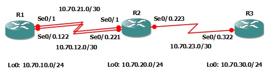 In this lab you will disable auto-summarization on all routers and configure R3 with 4 new loopback interfaces with the IP addresses of 10.30.0.0/24, 10.30.1.0/24, 10.30.2.0/24 and 10.30.3.0/24 and create a summary route that is sent to R2 via the point-to-point frame-relay link between R3 and R2.
Familiarize yourself with the following new command(s);
| Command | Description |
|---|---|
| ip summary-address rip n.n.n.n s.s.s.s | This command is executed in interface configuration mode to advertise a summary address out that particular interface. |
Lab Prerequisites
- If you are using GNS3 than load the Free CCNA Workbook GNS3 topology than start devices; R1, R2 and R3.
- Establish a console session with devices R1, R2 and R3 than load the initial configurations provided below by copying the config from the textbox and pasting it into the respected routers console.
!##################################################
!# Free CCNA Workbook Lab 7-8 R1 Initial Config #
!##################################################
!
enable
configure terminal
!
hostname R1
!
interface Loopback0
description ### SIMULATED NETWORK ###
ip address 10.70.10.1 255.255.255.0
!
interface Serial0/0
description ### PHYSICAL FRAME RELAY INTERFACE ###
no ip address
encapsulation frame-relay
serial restart-delay 0
no frame-relay inverse-arp
!
interface Serial0/0.122 point-to-point
description ### FRAME RELAY LINK TO R2 ###
ip address 10.70.12.1 255.255.255.252
frame-relay interface-dlci 122
!
interface Serial0/0
no shut
!
interface Serial0/1
description ### PPP Link TO R2 ###
ip address 10.70.21.1 255.255.255.252
encapsulation ppp
serial restart-delay 0
clock rate 128000
no shut
!
exit
!
router rip
version 2
network 10.0.0.0
timers basic 30 40 10 60
passive-interface Serial0/1
neighbor 10.70.21.2
!
end
!##################################################
!# Free CCNA Workbook Lab 7-8 R2 Initial Config #
!##################################################
!
enable
configure terminal
!
hostname R2
!
interface Loopback0
description ### SIMULATED NETWORK ###
ip address 10.70.20.1 255.255.255.0
!
interface Serial0/0
description ### PHYSICAL FRAME RELAY INTERFACE ###
no ip address
encapsulation frame-relay
serial restart-delay 0
no frame-relay inverse-arp
!
interface Serial0/0.221 point-to-point
description ### FRAME RELAY LINK TO R1 ###
ip address 10.70.12.2 255.255.255.252
frame-relay interface-dlci 221
ip rip triggered
ip rip send version 1 2
ip rip receive version 1 2
!
interface Serial0/0.223 point-to-point
description ### FRAME RELAY LINK TO R3 ###
ip address 10.70.23.1 255.255.255.252
frame-relay interface-dlci 223
!
interface Serial0/0
no shut
exit
!
interface Serial0/1
description ### PPP LINK TO R1 ###
ip address 10.70.21.2 255.255.255.252
encapsulation ppp
serial restart-delay 0
clock rate 128000
no shut
exit
!
router rip
version 2
network 10.0.0.0
timers basic 30 40 10 60
passive-interface Serial0/1
neighbor 10.70.21.1
!
end
!##################################################
!# Free CCNA Workbook Lab 7-8 R3 Initial Config #
!##################################################
!
enable
configure terminal
!
hostname R3
!
interface Loopback0
description ### SIMULATED NETWORK ###
ip address 10.70.30.1 255.255.255.0
!
interface Serial0/0
description ### PHYSICAL FRAME RELAY INTERFACE ###
no ip address
encapsulation frame-relay
serial restart-delay 0
no frame-relay inverse-arp
!
interface Serial0/0.322 point-to-point
description ### FRAME RELAY LINK TO R2 ###
ip address 10.70.23.2 255.255.255.252
frame-relay interface-dlci 322
ip rip advertise 10
ip rip triggered
ip rip send version 1 2
ip rip receive version 1 2
!
interface Serial0/0
no shut
exit
!
router rip
version 2
network 10.0.0.0
timers basic 30 40 10 60
default-information originate
!
end
Lab Objectives
- Disable auto-summarization on all routers in the network topology; R1, R2 and R3.
- Configure R3 with 4 new loopback interfaces using the ip addresses; 10.30.0.1/24, 10.30.1.1/24, 10.30.2.1/24 and 10.30.3.1/24
- Configure a RIP summary route to be advertised to R2 via Serial0/0.322 summarizing the 4 new networks into a single route.
- Verify your configuration by viewing the routing table on R2 and ensuring that R2 is learning the summary route and not four /24 subnets.
Lab Instruction
Objective 1. – Disable auto-summarization on all routers in the network topology; R1, R2 and R3.
R1>enable
R1#configure terminal
Enter configuration commands, one per line.  End with CNTL/Z.
R1(config)#router rip
R1(config-router)#no auto-summary
R1(config-router)#end
R1#
R2>enable
R2#configure terminal
Enter configuration commands, one per line.  End with CNTL/Z.
R2(config)#router rip
R2(config-router)#no auto-summary
R2(config-router)#end
R2#
R1>enable
R3#configure terminal
Enter configuration commands, one per line.  End with CNTL/Z.
R3(config)#router rip
R3(config-router)#no auto-summary
R3(config-router)#end
R3#
Objective 2. – Configure R3 with 4 new loopback interfaces using the ip addresses; 10.30.0.1/24, 10.30.1.1/24, 10.30.2.1/24 and 10.30.3.1/24
R3>enable
R3#configure terminal
Enter configuration commands, one per line.  End with CNTL/Z.
R3(config)#interface Lo 103000
R3(config-if)#ip add 10.30.0.1 255.255.255.0
R3(config-if)#interface Lo 103010
R3(config-if)#ip add 10.30.1.1 255.255.255.0
R3(config-if)#interface Lo 103020
R3(config-if)#ip add 10.30.2.1 255.255.255.0
R3(config-if)#interface Lo 103030
R3(config-if)#ip add 10.30.3.1 255.255.255.0
R3(config-if)#end
R3#
Objective 3. – Configure a RIP summary route to be advertised to R2 via Serial0/0.322 summarizing the 4 new networks into a single route.
R3#configure terminal
Enter configuration commands, one per line.  End with CNTL/Z.
R3(config)#interface Serial0/0.322
R3(config-subif)#ip summary-address rip 10.30.0.0 255.255.252.0
R3(config-subif)#end
R3#
Objective 4. – Verify your configuration by viewing the routing table on R2 and ensuring that R2 is learning the summary route and not four /24 subnets.
R2#show ip route
Codes: C - connected, S - static, R - RIP, M - mobile, B - BGP
       D - EIGRP, EX - EIGRP external, O - OSPF, IA - OSPF inter area
       N1 - OSPF NSSA external type 1, N2 - OSPF NSSA external type 2
       E1 - OSPF external type 1, E2 - OSPF external type 2
       i - IS-IS, su - IS-IS summary, L1 - IS-IS level-1, L2 - IS-IS level-2
       ia - IS-IS inter area, * - candidate default, U - per-user static route
       o - ODR, P - periodic downloaded static route

Gateway of last resort is 10.70.23.2 to network 0.0.0.0

     10.0.0.0/8 is variably subnetted, 8 subnets, 4 masks
R       10.30.0.0/22 [120/1] via 10.70.23.2, 00:00:04, Serial0/0.223
C       10.70.12.0/30 is directly connected, Serial0/0.221
R       10.70.10.0/24 [120/1] via 10.70.21.1, 00:00:07, Serial0/1
                      [120/1] via 10.70.12.1, 00:00:25, Serial0/0.221
R       10.70.30.0/24 [120/1] via 10.70.23.2, 00:00:04, Serial0/0.223
C       10.70.21.1/32 is directly connected, Serial0/1
C       10.70.20.0/24 is directly connected, Loopback0
C       10.70.21.0/30 is directly connected, Serial0/1
C       10.70.23.0/30 is directly connected, Serial0/0.223
R*   0.0.0.0/0 [120/1] via 10.70.23.2, 00:00:05, Serial0/0.223
R2#
To perform additional verification you can view R1’s routing table to verify if the route is being correctly summarized as a a single /22 or multiple /24 subnets.
R1#show ip route
Codes: C - connected, S - static, R - RIP, M - mobile, B - BGP
       D - EIGRP, EX - EIGRP external, O - OSPF, IA - OSPF inter area
       N1 - OSPF NSSA external type 1, N2 - OSPF NSSA external type 2
       E1 - OSPF external type 1, E2 - OSPF external type 2
       i - IS-IS, su - IS-IS summary, L1 - IS-IS level-1, L2 - IS-IS level-2
       ia - IS-IS inter area, * - candidate default, U - per-user static route
       o - ODR, P - periodic downloaded static route

Gateway of last resort is 10.70.21.2 to network 0.0.0.0

     10.0.0.0/8 is variably subnetted, 8 subnets, 4 masks
R       10.30.0.0/22 [120/2] via 10.70.21.2, 00:00:25, Serial0/1
                     [120/2] via 10.70.12.2, 00:00:03, Serial0/0.122
C       10.70.12.0/30 is directly connected, Serial0/0.122
C       10.70.10.0/24 is directly connected, Loopback0
R       10.70.30.0/24 [120/2] via 10.70.21.2, 00:00:25, Serial0/1
                      [120/2] via 10.70.12.2, 00:00:03, Serial0/0.122
R       10.70.20.0/24 [120/1] via 10.70.21.2, 00:00:00, Serial0/1
                      [120/1] via 10.70.12.2, 00:00:04, Serial0/0.122
C       10.70.21.0/30 is directly connected, Serial0/1
R       10.70.23.0/30 [120/1] via 10.70.21.2, 00:00:00, Serial0/1
                      [120/1] via 10.70.12.2, 00:00:04, Serial0/0.122
C       10.70.21.2/32 is directly connected, Serial0/1
R*   0.0.0.0/0 [120/2] via 10.70.21.2, 00:00:01, Serial0/1
               [120/2] via 10.70.12.2, 00:00:05, Serial0/0.122
R1#
As shown in R1’s routing table; 10.30.0.0/22 is being load balanced over the frame relay link and the point-to-point T1 link.
